Overload Relay Cep7 Diagram Neutral Wire - Jika kamu mencari artikel Overload Relay Cep7 Diagram Neutral Wire terlengkap, berarti kamu telah berada di blog yang benar. Setiap artikel diulas secara lengkap dengan penyajian bahasa yang enteng dipahami bagi orang awam sekalipun. itulah sebabnya web ini banyak diminati para blogger dan pembaca online. Yuk langsung saja kita simak ulasan Overload Relay Cep7 Diagram Neutral Wire berikut ini.
Overload Relay Cep7 Diagram Neutral Wire. View and Download Eaton Cutler-Hammer CEP7 Series instruction leaflet online. CEP7 overload relays do not work with Variable Frequency Drives DC Applications or Softstarters with braking options. CEP7S-EE is a 1-phase application overload relay packing all the features of the 3-phase CEP7-EE model. Easy and simple wiring diagram to make you learn easily watch the vid. The circuit diagram of the three-phase induction motors is shown in the figure below.
Chevy Lumina Starter Wiring Diagram Cutler-hammer cep7-m32 series Cutler-hammer cep7-a32 series Cutler-hammer cep7-m37 series Cutler-hammer cep7-a37. Variety of siemens overload relay wiring diagram. Manual reset or automatic reset can be selected with dip switches on the new CEP7-EE models. Electrical circuits are designed to handle a limited amount of electricity. Hence the overload relay gets heated up and it. This allows the cause of the over-load to be identified before the motor is restart-ed.
CEP7 overload relays do not work with Variable Frequency Drives DC Applications or Softstarters with braking options.
Dom 10 Inverter Circuit Diagram Overload Relay Connection Diagram. Siemens Overload Relay Wiring Diagram. September 16 2018 by Larry A. The wiring diagram of an overload relay is shown below and the connections of an overload relay symbol may seem like two opposite question marks otherwise like S symbol. Customers are encouraged to migrate to our E100 Overload Relays. Plus Overload Relay allows it to respond quickly to phase loss conditions.
Self-powered same wiring as standard bimetallic overload.
2006 Ford Mustang Fuel Pump Wiring Diagram View and Download Eaton Cutler-Hammer CEP7 Series instruction leaflet online. The overload relay has a selectable current setting based on the full load amp rating of the motor. The circuit diagram of the three-phase induction motors is shown in the figure below. Plus Overload Relay allows it to respond quickly to phase loss conditions. Siemens Overload Relay Wiring Diagram.
The specifications in relation to short-circuit protection for contactors and overload relays must be noted when selecting the rating of fuses or circuit-breakers.
Wiring Diagram 48 Volt Cushman Commander Heater bimetal overload relays. Rockwell Automation announces that as of April 2021 our Bulletin 193 IEC and 592 NEMA E1 Plus Electronic Overload Relays will be discontinued and no longer available for sale. Easy and simple wiring diagram to make you learn easily watch the vid. Not effective partly effective fully effective SST 081 91 M 2 SST 081 91 M 1 SST 081 91 M 3. If the overload current exceeds the setting of the relay for a sufficient length of time a set of contacts opens to protect the motor from damage. Typical reaction time is 3 seconds.
Plus Overload Relay allows it to respond quickly to phase loss conditions.
1997 Toyota Supra Wiring Diagram Original Self-powered same wiring as standard bimetallic overload. How does an overload relay protect from phase failures. AM in conjunction with the thermal overload relay. Series CEP7 Solid State Overload Relay Trip Curves and Wiring Diagrams Figure 1ÊTrip Curves Figure 2ÊWiring Diagrams 3-Phase Full Voltage Across-the-Line Starter1 1 10 100 1000 1284 6 10 200 800 600 400 20 80 60 40 2 8 6 42864 Class 10 Approximate Trip Time seconds Multiple of Full Load Current 1 100 1000 664 284 6 10 Class 20. Variety of thermal overload relay wiring diagram.
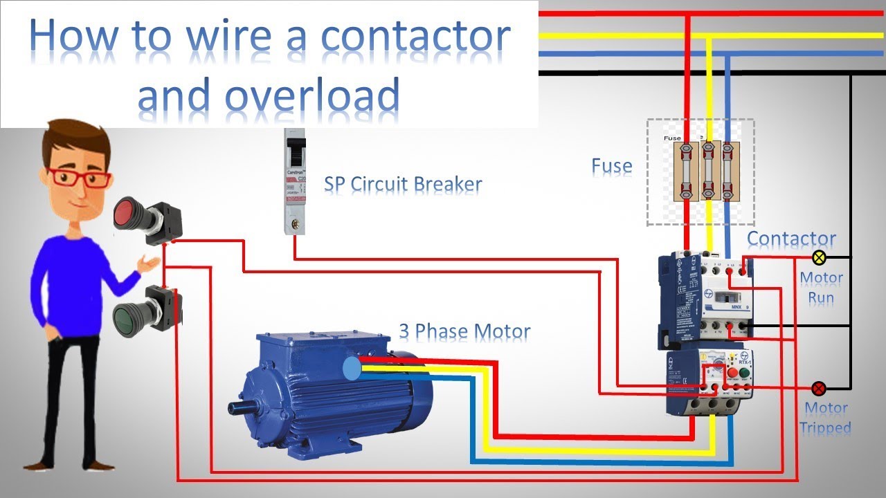
This article shows how to wire various motors using the Fuji series of contactors sold by.
Plc Hardware Wiring Diagram Rockwell Automation announces that as of April 2021 our Bulletin 193 IEC and 592 NEMA E1 Plus Electronic Overload Relays will be discontinued and no longer available for sale. E1 Plus Electronic Overload Relays. This allows the cause of the over-load to be identified before the motor is restart-ed. Cutler-hammer cep7-m32 series Cutler-hammer cep7-a32 series Cutler-hammer cep7-m37 series Cutler-hammer cep7-a37. Adjustment range of 51. Electrical circuits are designed to handle a limited amount of electricity.
Electrical circuits are designed to handle a limited amount of electricity.
Mitsubishi Eclipse Wiring Harness Diagram The overload relay has a selectable current setting based on the full load amp rating of the motor. Solid State Overload Relay. View and Download Eaton Cutler-Hammer CEP7 Series instruction leaflet online. Typical reaction time is 3 seconds. Manual reset or automatic reset can be selected with dip switches on the new CEP7-EE models.
The circuit diagram of the three-phase induction motors is shown in the figure below.
Dodge Caravan 1998 Wiring Diagram If anyone of the phase is interrupted the current through the other two phases rises to 173 times the normal value. Overload Relay Connection Diagram. Variety of thermal overload relay wiring diagram. The wiring diagram of an overload relay is shown below and the connections of an overload relay symbol may seem like two opposite question marks otherwise like S symbol. Customers are encouraged to migrate to our E100 Overload Relays. Circuits are made up of wiring a breaker or a fuse in old wiring systems and devices such as light fixtures appliances and anything plugged into an outlet.
Cutler-Hammer CEP7 Series relays pdf manual download.
2003 Hyundai Sonata Wiring Diagrams Easy and simple wiring diagram to make you learn easily watch the vid. Variety of thermal overload relay wiring diagram. September 16 2018 by Larry A. Variety of siemens overload relay wiring diagram. Easy to Select and Apply Straightforward installation The self-powered design means that the E1 Plus Overload Relay installs in the same manner as traditional overload relays.
Rockwell Automation announces that as of April 2021 our Bulletin 193 IEC and 592 NEMA E1 Plus Electronic Overload Relays will be discontinued and no longer available for sale.
Wiring Diagram For 1984 Monte Carlo Circuits are made up of wiring a breaker or a fuse in old wiring systems and devices such as light fixtures appliances and anything plugged into an outlet. CEP7S-EE is a 1-phase application overload relay packing all the features of the 3-phase CEP7-EE model. Rockwell Automation announces that as of April 2021 our Bulletin 193 IEC and 592 NEMA E1 Plus Electronic Overload Relays will be discontinued and no longer available for sale. Typical reaction time is 3 seconds. Variety of siemens overload relay wiring diagram. Solid-state overload relays are available through 1000 amperes with available selection for Class 10 15 20 and 30 with ManualAutomatic Reset.
Heater bimetal overload relays.
Sears Lawn Tractor Manual Or Belt Diagram Variety of siemens overload relay wiring diagram. Self-powered same wiring as standard bimetallic overload. It shows the components of the circuit as simplified forms and the power and also signal links between the gadgets. CEP7-EE is a full featured selectable trip class 10 15 20 30 3-phase application overload relay with provi - sion for field mountable modules to handle remote reset jam protection and other modules previously avail - able only in higher priced electronic overload relays. Our Bulletin 193592 E300 networked and E200 non-networked Electronic Overload Relays are the newest technologies for overload protection.
CEP7 Pass-Thru models are available in up to 27 amperes for the ED1 and EE models.
Wiring Diagram Motor 1 Fasa Customers are encouraged to migrate to our E100 Overload Relays. Variety of siemens overload relay wiring diagram. Solid State Overload Relay. Typical reaction time is 3 seconds. How does an overload relay protect from phase failures. It shows the components of the circuit as simplified shapes as well as the power and signal links between the tools.
What Is an Electrical Circuit Overload.
Porsche Cdr 24 Wiring Diagram With adjustable bimetallic overload relays. With adjustable bimetallic overload relays. Adjustment range of 51. E1 Plus Electronic Overload Relays. Rockwell Automation announces that as of April 2021 our Bulletin 193 IEC and 592 NEMA E1 Plus Electronic Overload Relays will be discontinued and no longer available for sale.
CEP7S-EE is a 1-phase application overload relay packing all the features of the 3-phase CEP7-EE model.
Dodge O2 Sensor Wiring Diagram Cutler-Hammer CEP7 Series relays pdf manual download. CEP7S-EE is a 1-phase application overload relay packing all features of the 3-phase CEP7-EE model. Most industrial applications usually call for an overload relay that must be manually reset in the event of a trip. Variety of thermal overload relay wiring diagram. Not effective partly effective fully effective SST 081 91 M 2 SST 081 91 M 1 SST 081 91 M 3. The overload relay workingfunction is discussed below.
What Is an Electrical Circuit Overload.
Nissan Leaf 2 User Wiring Diagram Hence the overload relay gets heated up and it. Although there are several types of overload relays available in the market however the most frequent type of relay is the. Rockwell Automation announces that as of April 2021 our Bulletin 193 IEC and 592 NEMA E1 Plus Electronic Overload Relays will be discontinued and no longer available for sale. A wiring diagram is a streamlined standard pictorial representation of an electric circuit. Hence the overload relay gets heated up and it.
Circuits are made up of wiring a breaker or a fuse in old wiring systems and devices such as light fixtures appliances and anything plugged into an outlet.
The Magic Mirror Concerning A Lonely Princess A Foundling Girl A Scheming King And A Pickpocket Squirrel With adjustable bimetallic overload relays. Rockwell Automation announces that as of April 2021 our Bulletin 193 IEC and 592 NEMA E1 Plus Electronic Overload Relays will be discontinued and no longer available for sale. Magnetic contactor starter essentially consists of a set of start and stop push buttons with associated contacts overload and underload protective devicesThe start push button is a momentary contact switch that is held normally open by a spring. A wiring diagram is a streamlined standard pictorial representation of an electric circuit. DOL STARTER Control and Power wiring by using a fuse contactor Overload relay motor. CEP7S-EE is a 1-phase application overload relay packing all features of the 3-phase CEP7-EE model.
The specifications in relation to short-circuit protection for contactors and overload relays must be noted when selecting the rating of fuses or circuit-breakers.
2003 F 250 Fuse Box Diagram Efficiency of protection device. Easy to Select and Apply Straightforward installation The self-powered design means that the E1 Plus Overload Relay installs in the same manner as traditional overload relays. CEP7-EE is a full featured selectable trip class 10 15 20 30 3-phase application overload relay with provi - sion for field mountable modules to handle remote reset jam protection and other modules previously avail - able only in higher priced electronic overload relays. Series CEP7 Solid State Overload Relay Trip Curves and Wiring Diagrams Figure 1ÊTrip Curves Figure 2ÊWiring Diagrams 3-Phase Full Voltage Across-the-Line Starter1 1 10 100 1000 1284 6 10 200 800 600 400 20 80 60 40 2 8 6 42864 Class 10 Approximate Trip Time seconds Multiple of Full Load Current 1 100 1000 664 284 6 10 Class 20. DOL STARTER Control and Power wiring by using a fuse contactor Overload relay motor.
Situs ini adalah komunitas terbuka bagi pengguna untuk menuangkan apa yang mereka cari di internet, semua konten atau gambar di situs web ini hanya untuk penggunaan pribadi, sangat dilarang untuk menggunakan artikel ini untuk tujuan komersial, jika Anda adalah penulisnya dan menemukan gambar ini dibagikan tanpa izin Anda, silakan ajukan laporan DMCA kepada Kami.
Jika Anda menemukan situs ini bagus, tolong dukung kami dengan membagikan postingan ini ke akun media sosial seperti Facebook, Instagram dan sebagainya atau bisa juga simpan halaman blog ini dengan judul Overload Relay Cep7 Diagram Neutral Wire dengan menggunakan Ctrl + D untuk perangkat laptop dengan sistem operasi Windows atau Command + D untuk laptop dengan sistem operasi Apple. Jika Anda menggunakan smartphone, Anda juga dapat menggunakan menu laci dari browser yang Anda gunakan. Baik itu sistem operasi Windows, Mac, iOS, atau Android, Anda tetap dapat menandai situs web ini.